Wifi- enabled Autonomous Driving Robot
The objective of this project is to create a robot capable of navigating a course with a variety of obstacles using a variety of different sensors and measurement metrics. The design criteria for the robot include path navigation through a course with multiple 90 degree bends, color and obstacle detection, turn indication, position and velocity estimation, and control through a remote device, also known as ‘untethered’. These deliverables will be accomplished through a variety of different sensors, motors, and LEDs. A control algorithm will be implemented to determine the robot’s path and movements based on ultrasonic readings. A ring of LEDs fixed to the robot will indicate any turns that need to be made, or if the wall color has changed.
When tested, our robot met all of the design criteria and navigated the course successfully. It also was able to indicate when a wall was colored red vs. blue. Lastly, this project was completed under the predetermined $150 budget.
Electronic Design
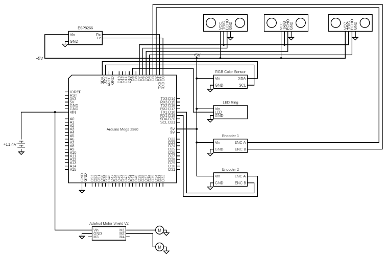
There were four major domains of this project handled with electronics: Control Logic, Actuation, Sensing, and Communication. All of the control logic was handled onboard an Arduino Mega microcontroller. This controller was selected because it was able to provide us with a sufficient number of digital/analog/interrupt pins, output current, and output voltage to support all of our hardware. Actuation was handled using an Adafruit V2 Motor shield, which allowed us to drive two 12V geared motors with a current exceeding the 200mA limit of the Arduino. A 11.1V 450mAh 45C LiPo battery was selected in order to meet the power demands of all electrical systems on the robot for a duration far exceeding a 60s test. We selected 12V geared motors (20:1) with built in quadrature encoders to meet both the speed and torque requirements of the track, as well as increasing our ability to measure wheel rotation.
Mechanical Design
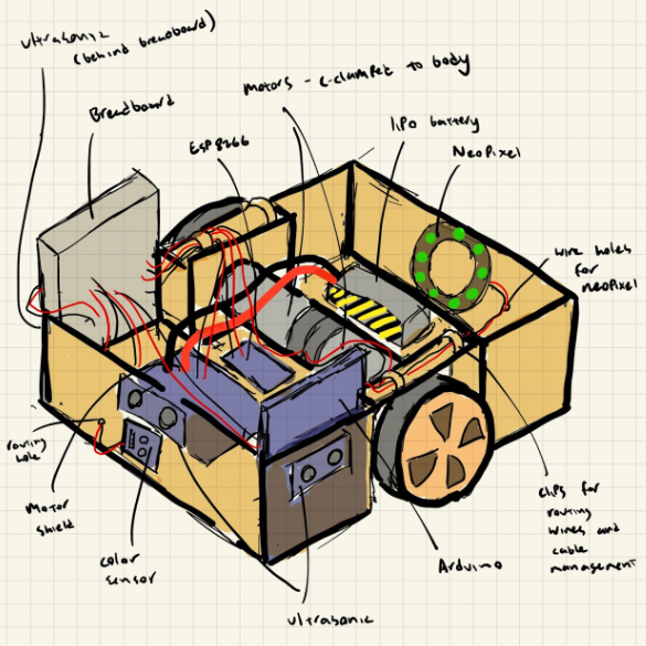
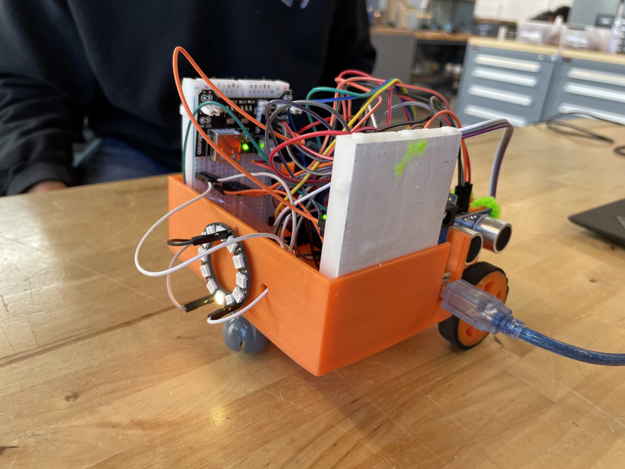
Our design goal was to create a compact and reliable mechanical system to allow for easy and repeatable course navigation. We kept the width of the car body to roughly 20 cm as the width of the course was only 23.5cm and we wanted as much clearance as possible on either side. It was also designed with serviceability in mind, in the event that we had to diagnose electrical issues. There are a couple important aspects to note. First, the location of the wheels and hardware components inside the car are shifted to the middle of the body so that the center of mass will be almost directly over the driving motors. This is to ensure that the car has the lowest possible risk of slipping while on an uphill incline. The wheels driven by our motos were custom 3d printed using PLA and TPU. The diameter of the wheel was chosen based on the required course completion speed of 60s. We also included a ball bearing mounted under the car body towards the rear of the vehicle to ensure bar balance. Secondly, there are holes in the body that allow electrical components such as the arduino and the neopixel to stay securely in one place, while still being accessible for pin swapping and breadboard prototyping. We split major systems into different breadboards for easier troubleshooting. This proved useful when we encountered issues with our arduino not picking up signals from the echo pins on our ultrasonic sensors. If we had more time, we would have switched to a protoboard once our breadboard prototype was finished, especially because we had issues with wires falling out of the breadboard in the weeks leading up to testing.
Algorithims and PID control
We used a PID algorithm to control our motors. This allowed us to maintain a contant velocity even when the required course torque changed (for example on the hills). We used a proportional controller to controll the direction of the robot. The robot would measure the distance from each side of the car to the wall, calculate the different, and adjust the target speeds of the motors to guide the robot on the optimal path.
Results
Estimation of Uncertainty
We used dead reckoning to estimate the position of the robot with a no-slip wheel assumption. This creates uncertainty in distance measurements, as wheel slippage is known to happen in the real world. To estimate the uncertainty, we commanded the robot to drive forwards 90cm for 10 trials, measuring the true displacement each time. We found that the average error for a 90cm trajectory was 0.62cm, yielding an uncertainty rate of 0.7% for distance traveled.
In terms of measuring the uncertainty of our ultrasonic sensors, we verified that each sensor could detect the distance from a wall within 0.5cm during the testing of our sensor platform.
Course Navigation
Prior to testing, we ensured that the ultrasonic sensors were working properly by gauging the LED ring state while positioning our hands at various distances from the sensors. In a similar manner, both a blue and red wall were placed in front of the color sensor to ensure that color was read properly. Additionally, we tested the robot on isolated corner segments to ensure that corner turning events would be triggered properly.
The robot was deployed on the test track a number of times. Due to the autonomous nature of the project, not much was done while testing was conducted, however we did take videos to monitor the performance of the robot as well as the LED indications of the robot’s planned motions. Track testing was mostly successful with all systems functioning as intended. We were the only team in the class to complete the course on time and fully wireless. The following video demonstrates the robot’s ability to meet the 60 second speed requirement, ability to detect a red wall (indicated by a purple 🙂 on the ring), and the ability to traverse a 5 degree grade both up and down.